


Product images

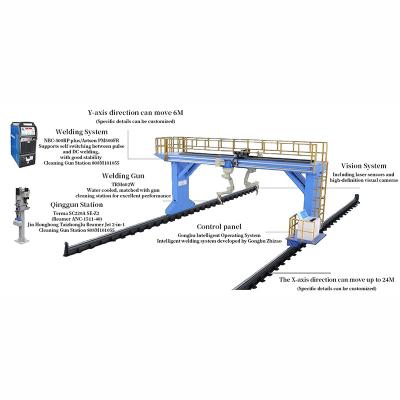
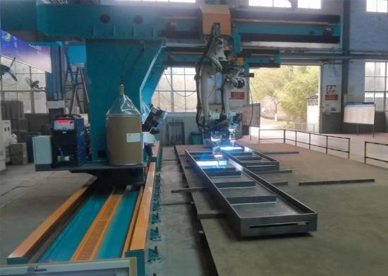
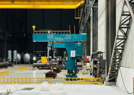
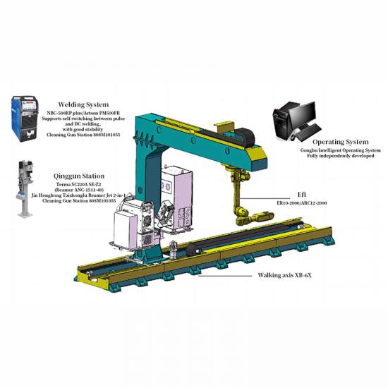
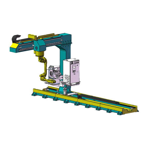
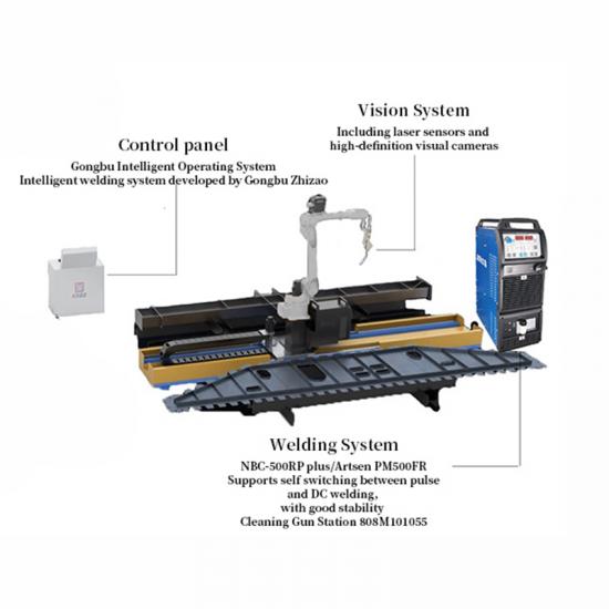
Ssembly diagram of the Gantry Eight-Axis Workstation

Parameters of the Gantry Eight-Axis Workstation
| subitem | unit | content |
| applicable scenarios | / | Welding of structural components such as H-shaped steel beams, columns, bridge slabs, and large diaphragms (with a width less than 5/7 meters) |
| equipment specifications | m | 24*7.5*3.8、24*9.5*3.8 |
| total power | KW | 34 |
| Maximum working range | m | 22*5*0.45、22*7*0.45 |
| average welding efficiency | m/day | 180~240(The structural types are different) |
Performance of the Gantry Dual-Machine Eight-Axis Workstation
| Application processes | Cutting, marking, welding |
| Environmental protection equipment | optional equipment |
| Work Coordinate System | PCS1、PCS2、PCS3 |
| Working range | 22000*5000*450 |
| Working hours | 7*20H |
| Welding Process Package | CO2/80% CO2+20%AR solid core carbon steel, CO2 flux-cored carbon steel DC and pulse welding |
| Welding Material Type | spool packaging、drum packaging |
| Applicable scenarios | Welding of longer structural components such as H-shaped steel beams, columns, and bridge slabs |
| Motion mode | Eight-axis linkage |
| Auxiliary Axis | X and Y axis compensation additional axes, allowing both robots to cover the entire gantry workspace |
Workflow of the Gantry Dual-Machine Eight-Axis Workstation
1)Manually or via conveyor chain, transport the components to be welded to the workstation frame, positioning them near point P;
2)(Simultaneously or in advance) Operators rotate the model consistently and create nodes based on the component number and placement;
3)If the placement deviation is too large, use a camera to identify the component's positioning point P. If the placement is close enough, operators directly load the model and initiate scanning;
4)After scanning is complete, the system initiates welding;
5)Once the welding of the entire component is completed, transport the component to the subsequent workstation. If there is no component model, the equipment can be operated for welding using visual interaction. After placing the component on the workstation, operators take photos of the welding areas using a camera, match the process, and initiate scanning for welding. Compared to model-driven operations, this method increases the relative workload for operators

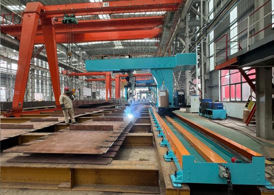
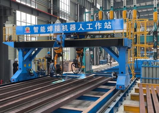
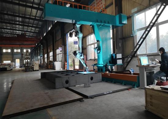
Applicable Component Display (Partial)


 IPv6 network supported