


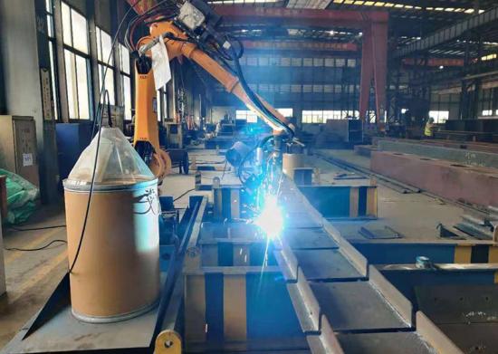
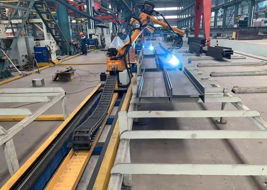
Product images
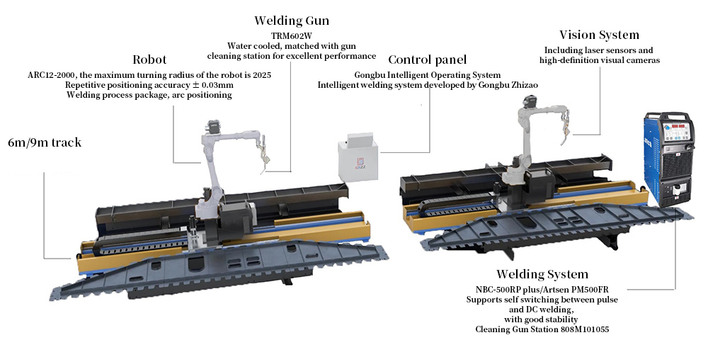
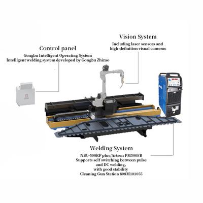
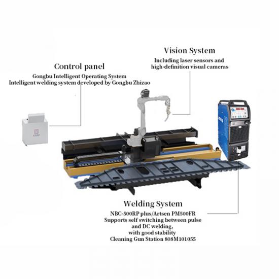
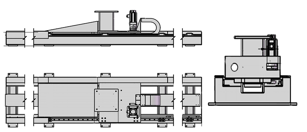
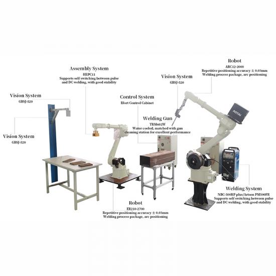
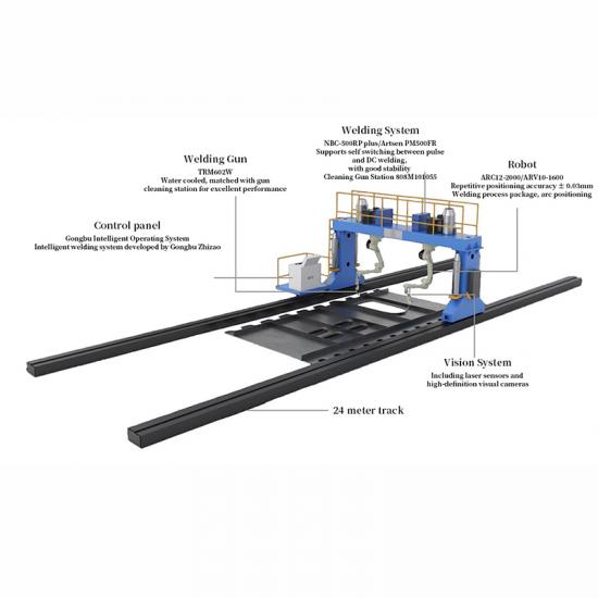
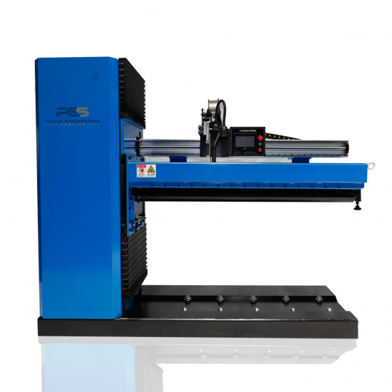
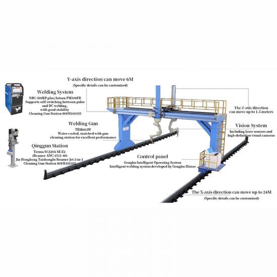
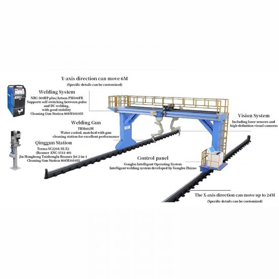
Ssembly diagram of the Ground Track Intelligent Workstation
Parameters of the Ground Track Intelligent Workstation
| Equipment Name | Ground Track Intelligent Workstation |
| Equipment Model | GBDG-6X/GBDG-9K/GBDG-12X |
| Supporting System Software | GBZZOS |
| Number of Additional Axes | 1 for increasing length direction travel |
| Occupied Space for One Set | Dual workstation: 9000*5800mm (including 9-meter track, safety aisle, and operating platform) |
| Applicable Weld Seam Types | Butt welds, fillet welds, multi-pass multi-layer corner welds, bevel groove welds |
| Standard Adaptation to Component Specifications | 1200:550mm (Width:Height), length matches the equipment model |
| Industry Component Types | Steel structure, H-beam structure, box structure, bridge and ship plate unit structure |
Performance of the Ground Track Intelligent Workstation
| Application processes | Cutting, marking, welding |
| Environmental protection equipment | optional equipment |
| Work Coordinate System | PCS2、PCS3(On both sides of the track) |
| Working range | 6500*1200*300 |
| Working hours | 7*20H |
| Welding Process Package | CO2/80% CO2+20%AR solid core carbon steel, CO2 flux-cored carbon steel DC and pulse welding |
| Welding Material Type | spool packaging、drum packaging |
| Applicable scenarios | Welding of structural components such as H-shaped steel beams, columns, bridge and ship plates |
| Motion mode | Seven-axis linkage |
| Auxiliary Axis | Optional Ground Track and Gantry |
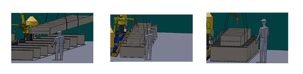
Workflow of the Ground Track Intelligent Workstation
1) The workpiece to be welded is transferred to the workstation by manual labor or a conveyor chain, positioning it near point P;
2) (Simultaneously or in advance) Operators rotate the model consistently based on the component number and orientation, creating nodes;
3) If there is significant deviation in placement, the component's positioning at point P is first identified using a camera;
4) If the placement is close enough, operators directly load the model and initiate scanning. At this point, operators may also hoist another component onto the second set of equipment racks or another workstation of this equipment to perform the aforementioned steps;
5) After the scanning is completed, the system initiates welding:
6) Once the entire component welding process is complete, the component is transferred to the subsequent workstation for further work.
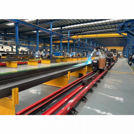
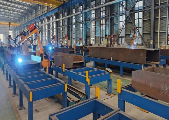
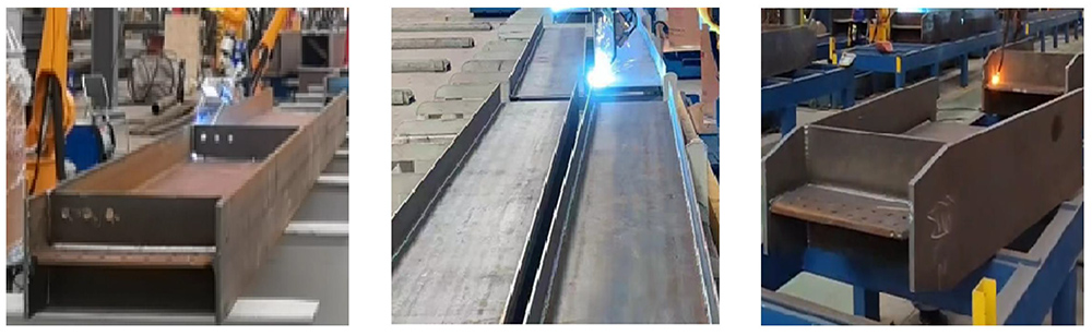
Applicable Component Display (Partial)


 IPv6 network supported