


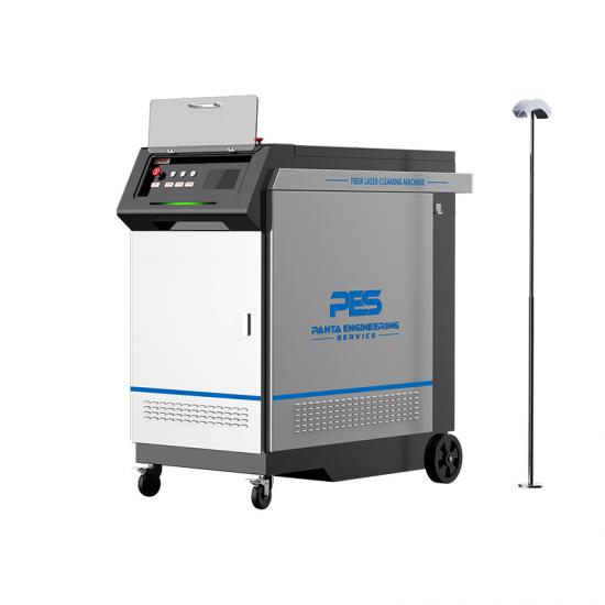
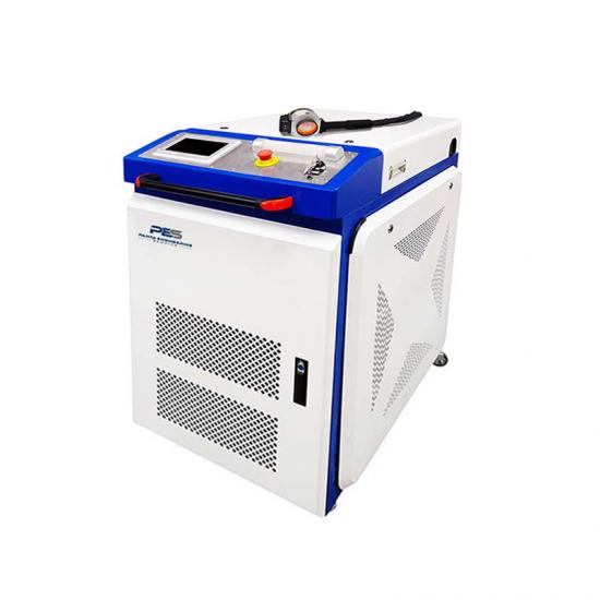
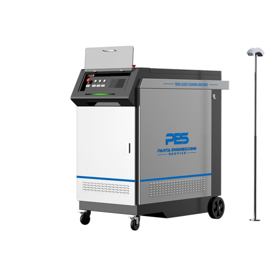
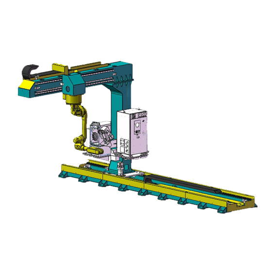
Product images

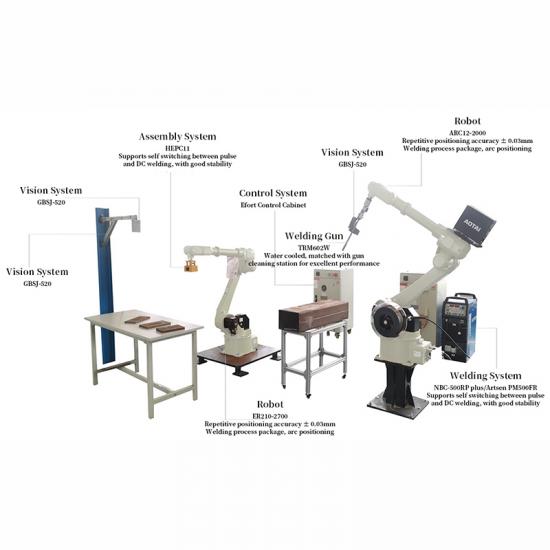
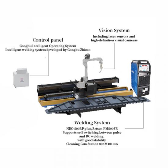
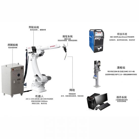
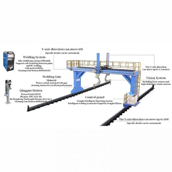
Workstation Configuration
| Robot | ARC12-2000/ER50-2100/ER210-2700 | Efort |
| Welding Power Supply | NBC-500 RP plus/Artsen2 PM500FR Supports pulse and DC welding free switching with good stability | AOTAI,MEGMEET |
| Tools | Can accommodate welding guns, cutting heads, and electromagnets | Selection based on customer requirements |
| Vision System | GBSJ-520 Includes laser sensors, high-definition vision cameras | Gongbu |
| Intelligent Welding System | Gongbu Intelligent Manufacturing develops intelligent welding systems for non-standard fields, leading the international level | Gongbu |
Assembly and Welding Joint Workstation Parameters
| subitem | unit | content |
| applicable scenarios | / | Assembly of square tube beams and columns, assembly welding of primary and secondary beams of light steel H-beam in prefabricated houses |
| equipment specifications | m | Width of 5 meters * length to fit |
| total power | KW | 37 |
| structural component requirements | m | Width ≤ 1200, part plate weight ≤ 50KG |
| average welding efficiency | node | 40~60 nodes (different types of nodes) |
Performance of Assembly and Welding Joint Workstation
| Application processes | Automatic assembly, welding |
| Environmental protection equipment | optional equipment |
| Work Coordinate System | PCS2、PCS3 |
| Working hours | 7*20H |
| Welding Process Package | CO2/80% CO2+20%AR solid core carbon steel,CO2flux-cored carbon steel DC and pulse welding |
| Welding Material Type | spool packaging、drum packaging |
| Walking Auxiliary Axis | Optional Ground Track and Gantry |
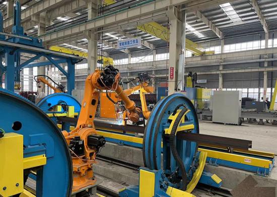
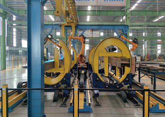
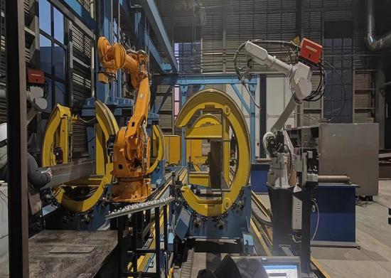
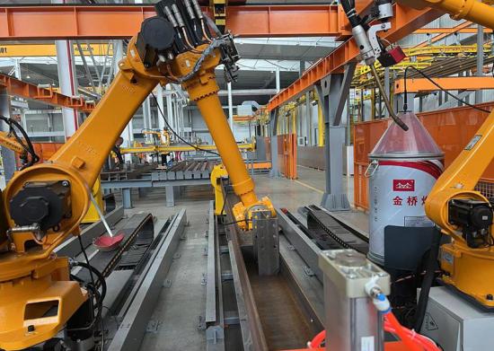
Assembly and Welding Joint Workstation Workflow
1)At the front end of the production line, coding and cutting of materials are carried out sequentially according to the task list;
2)The conveying AGV transports the parts boards required for the planned tasks to the material platform position;
3)The intelligent assembly and welding system retrieves component models according to the task list and sends signals to each device at the workstation to be in position;
4)The indexing mechanism arrives at the docking station and triggers a signal, the gantry grabs the component and places it into the indexing mechanism;
5)After clamping by the indexing machine, the assembly robot determines the position of the component through visual scanning. The assembly robot starts grabbing the component boards for assembly based on the model and visual information (positioning and identification of parts) on the part table;
6)Welding robot starts spot welding, seam welding. After completing one side, the indexing machine flips to weld the other sides of the component boards;
7)After welding is completed, the system sends a signal, and the gantry hoists the finished components onto the AGV at the buffer station or the docking station (priority);
8)The finished components are transported to the manual grinding station by AGV or overhead crane.

Applicable Component Display (Partial)


 IPv6 network supported