Mar 17, 2022
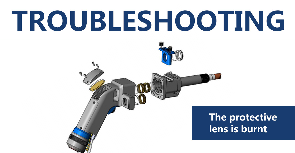
Welding head problem: burning protective lens
Manifestation: In a short period of time, the protective lens is damaged and there is a burning spot, and the light-emitting surface of the protective lens is dotted with damaged spots, showing black or white black spots The analysis of causes: Due to the influence of process/method/setting, etc., the anti-slag causes damage, and very few are abnormal laser light output Solution: ①Appropriately increase the air pressure. Usually, the flow rate is not less than 15, and the pressure is not less than 0.3-0.6Mpa ②When welding, try to weld the welding gun and the plate at 30-70°, not vertical ③Set the parameters as much as possible to slowly rise and fall, such as the on/off delay of 200-500ms, the on/off optical power 20%, and the on/off progressive time 200-300ms, as shown in the figure, you cannot set 0 ④When welding aluminum and galvanized sheets, this material will damage the lens more easily than other materials, so the minimum power should be used for welding. ⑤The quality of the protective mirror also determines the durability of its use. It is recommended to use the original lens ⑥At high power, the loss of the lens will increase compared to low power, which is an uncontrollable range ⑦When the above cannot be handled, you can replace the F200 focusing lens + lengthened and wide scale tube to reduce splashes (additional purchase is required)
View More


 IPv6 network supported