

Treatment of welding joint problems: Abnormal treatment of air outlet but unable to feed wire
Apr 11, 2022Operation logic: The wire feeder is connected to the 5 / 6 pin of the signal interface 2 of the control box through the two core plug signal wire at the tail. When the system is running, the 5 / 6 pin is connected after the built-in relay on the main board of the control box is pulled in, and the wire feeder starts to work (i.e. the 5 / 6 pin is controlled on and off)
In case of outgassing but no wire feeding:
Let's first decide whether there is a problem with the control of the wire feeder
Click [manual wire feeding] on the front panel of the wire feeder to check whether the wire feeding wheel is running
1. The wire feeder does not work, and there is a problem with the wire feeder itself
2. Continue to operate the wire feeder according to the following operation
According to its operation logic, we first short-circuit the signal line of the wire feeder, pull it out from pin 5 / 6 and then short-circuit the signal line (not pin 5 / 6)
Then there are two situations
1. If the wire feeder operates, it can be determined that the wire feeder is OK and the 5 / 6 pin of the system control board is wrong
2. If the wire feeder does not operate, it can be judged that the signal line is open circuit and the signal line can be checked
The following is the first case. The problem of pin 5 / 6 of signal interface 2 of control board is handled
Operation logic of control card:
When the system is running, the 3 / 4 pin of signal interface 2 outputs 24V, the 5 / 6 pin is connected, and the two groups of signals are synchronized (excluding setting delay)
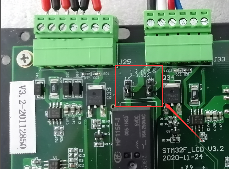
The wire feeding signal (pin 5 / 6) has a built-in jump cap (J10 * j11). By default, the jump cap uses a relay to control the on-off at 1 / 2 (as shown in the figure below). If the jump cap is at 2 / 3, MOS is used to control the on-off
Exception handling scheme:
If the system is running, after the 3 / 4 pin outputs 24V (i.e. air outlet state), but the 5 / 6 pin is blocked, try to put the jump cap at 2 / 3 and choose to use MOS control
Please note that if MOS control is used, the two signal lines are distinguished by ± 2. Therefore, if you use MOS control and there is an abnormality (direct wire feeding or no wire feeding), replace the signal lines
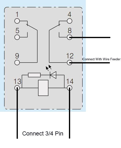
When the MOS cannot be used, the external relay (DC24V) can be used to control the pull in or replace the board
The signal sent by the external 4 / 4 pin of the relay is defined as follows
(The normally open pin of relay is used for two core signal of wire feeder)

合肥邦镭激光科技有限公司


 IPv6 network supported